Leave Your Message

What Is a Westbond Wire Bonder Used For?

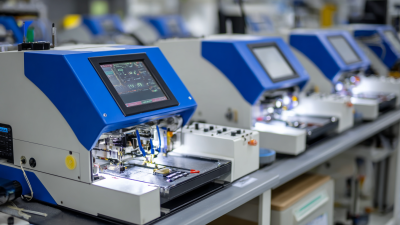
A Westbond Wire Bonder is used to create reliable electrical connections between semiconductor die pads and package leads, substrates, or circuit traces. It places extremely fine gold, copper, or aluminum wire with controlled force, heat, and ultrasonic energy. The result may look delicate, yet each bond must survive vibration, thermal cycling, humidity, and years of electrical use.

This equipment supports semiconductor assembly, LED production, MEMS devices, sensors, power modules, and laboratory prototypes. Ball bonding suits many fine-pitch integrated circuits, while wedge bonding handles aluminum wire, power devices, and specialized packages. SEMI reported global semiconductor manufacturing equipment sales of $106.3 billion in 2023, reflecting continued investment across the chip-production chain. Yole Group’s advanced-packaging reports also identify wire bonding as an established technology that remains important beside newer interconnection methods.

John H. Lau, a recognized semiconductor-packaging authority, has stated, “Wire bonding is still the most popular interconnection technology.” That observation helps explain the continued relevance of the Westbond Wire Bonder. It offers process visibility, adjustable bonding parameters, and practical flexibility for development and production work. Operators can inspect a bond under a microscope, adjust loop height, and test pull strength almost immediately. Small details decide reliability.

The choice is not automatic. Bond pitch, wire material, die layout, throughput, and package design must be evaluated together. A Westbond machine may be highly effective, but poor setup can still produce weak bonds, lifted wires, or inconsistent loops. That limitation matters. Performance depends on both equipment capability and disciplined process control.
What Is a Westbond Wire Bonder Used For?

What a WestBond Wire Bonder Is and Its Role in Semiconductor Assembly

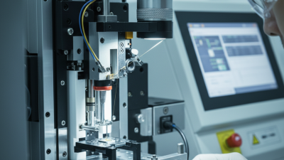
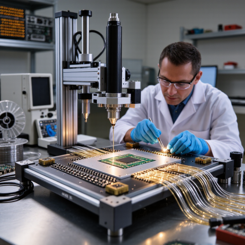
A wire bonder is a precision assembly machine used to connect a semiconductor die with its package leads or substrate. It forms tiny electrical links after the die has been attached. During operation, a capillary guides metal wire, presses it onto a bond pad, and creates a controlled connection through heat, pressure, ultrasonic energy, or combined methods. The wire may be gold, copper, or aluminum, depending on the device design and process limits. The machine controls bond force, ultrasonic power, loop height, wire length, and placement accuracy. Every setting matters.

In semiconductor assembly, the bonder works between die attach and final encapsulation. It can create ball bonds, wedge bonds, or specialized connections for power devices and sensors. Operators inspect pad condition, wire tension, capillary wear, and alignment before production. A microscope may show a clean first bond and a narrow second bond on the leadframe. Pull tests and shear tests measure mechanical strength. Electrical checks confirm stable current flow. These checks are practical evidence, not paperwork.

In practical assembly work, stable results depend on material control as much as machine accuracy. Oxidized copper wire, contaminated pads, or a worn capillary can create weak bonds. The machine cannot fix every upstream mistake. Overly tight process windows may also slow production and hide useful variation. Engineers should record failures, change one parameter at a time, and repeat testing. That discipline makes the bonder a dependable link between microscopic geometry and a working semiconductor package.
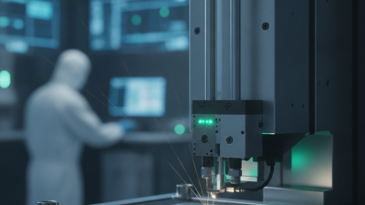
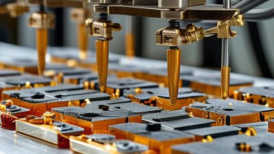
How Ultrasonic, Thermosonic, and Wedge Bonding Create Electrical Links

A wire bonder creates tiny electrical links between a chip and its package leads. On the production floor, alignment matters as much as force. Ultrasonic bonding uses high-frequency vibration to scrub oxides and form a solid-state joint. It usually needs no solder. The bond footprint can be only a few hundred micrometres wide. Small errors matter. The WSTS Spring 2024 Forecast valued global semiconductor sales at $611.2 billion, up 16% from 2023. That growth increases pressure for repeatable interconnects, not merely faster machines.

Thermosonic bonding combines heat, ultrasonic energy, and controlled pressure. A heated stage softens the wire and lowers the required bonding energy. This approach supports fine wires and sensitive surfaces, though excessive heat can damage materials. Engineers monitor bond force, ultrasonic power, time, temperature, and pull strength. A shiny bond may still be weak. It happens. Reliability testing must expose that risk.

Wedge bonding feeds wire through a tool that presses it at changing angles. It suits aluminium wire, power devices, and layouts requiring low loops. It can also handle ribbon-like conductors. SEMI’s 2024 World Fab Forecast projected semiconductor manufacturing equipment investment near $97 billion in 2024. That figure shows the scale behind process decisions, but forecasts are not guarantees. Operators still need microscopy, destructive pull tests, and documented control limits. The right method depends on metallurgy, pitch, loop height, and thermal budget.

Which Devices Use 15–500 µm Bond Wires in Production

A wire bonder is used to connect semiconductor chips with their package leads or substrate traces. It places extremely fine metal wires between two electrical points. In production, wire diameters from 15 to 500 µm serve very different device families. The correct size depends on current, pitch, loop height, thermal stress, and required mechanical strength.

Small wires, often 15–50 µm, appear in memory chips, microprocessors, image sensors, radio-frequency modules, and compact consumer electronics. They suit dense layouts with narrow pad spacing. LED packages and optical sensors also use fine wires, although their bonding surfaces can be sensitive to heat and contamination. During process checks, engineers inspect heel cracks, lifted bonds, wire sag, and inconsistent loop shapes. Tiny defects matter.

Larger wires, commonly 75–300 µm, support power semiconductors, automotive control modules, battery systems, and industrial inverters. Some high-current devices use wires approaching 500 µm, where low electrical resistance and strong thermal performance are essential. A thick aluminum wire may connect a power die to a lead frame, while copper wire can improve conductivity when the materials and bonding conditions are compatible. Production teams must control ultrasonic energy, bonding force, surface cleanliness, and temperature. It is not always simple. A larger wire does not automatically create a better connection. Excessive force can damage the chip, and insufficient energy can leave a weak bond. Reliability testing should include thermal cycling, pull tests, shear tests, and cross-sectional inspection.

How Bond Force, Temperature, and Ultrasonic Power Affect Bond Quality

A wire bonder connects fine metal wire between semiconductor pads, leads, or package substrates. It creates electrical paths through controlled pressure, heat, and ultrasonic vibration. Bond quality depends on how these settings interact, not on one number alone.

Bond force Bond force presses the wire against the bonding surface. Too little force can cause weak contact or poor wire deformation. Too much force may damage soft pads or create hidden cracks.

Temperature Temperature can soften materials and improve bonding consistency. Excessive heat, however, may affect sensitive components or metallization layers.

Ultrasonic power Ultrasonic power helps remove surface films and forms the bond through friction. Insufficient power can leave an unstable interface. Excessive power can thin the wire, damage the pad, or weaken the heel.

In production, engineers usually adjust one parameter at a time. They inspect the bond shape, measure wire deformation, and perform pull or shear tests. A healthy bond often shows consistent contact without deep pad marks.

The first pass is rarely perfect. Material batches, wire diameter, surface finish, and machine alignment can shift the result. Small adjustments matter.

Process records should include force, temperature, ultrasonic settings, and test results. This evidence supports repeatability and helps identify gradual equipment drift.

No setting works perfectly for every assembly. Careful validation remains necessary.

How MIL-STD-883 and JEDEC Tests Verify Wire-Bond Reliability

A wire bonder connects semiconductor chips to package leads using fine metal wire.

It creates controlled bonds through heat, pressure, ultrasonic energy, or a combination of these methods. In production, the machine must place each wire accurately, even when pads are tiny and closely spaced. A stable bond supports electrical performance and protects the assembly from vibration, heat, and daily operating stress.

MIL-STD-883 provides test methods for microelectronic devices. Engineers may use wire pull and bond shear tests to measure mechanical strength. They can also apply temperature cycling, moisture exposure, vibration, and mechanical shock. JEDEC test standards add widely recognized procedures for package reliability and environmental performance.

These tests do not prove that every bond will survive forever. They reveal weak process settings, contamination, poor surface preparation, or unsuitable wire materials. That distinction matters.

Tips: Record bond force, ultrasonic power, temperature, and loop height during production. Inspect sample bonds under magnification. A clean-looking connection can still fail a pull test. Keep test results linked to lot numbers and operator records. In practice, small variations can become important. Even experienced teams should question unusually perfect data, because testing errors and sampling limits can hide defects. A reliable wire bonder is therefore only one part of reliability control. Process discipline and repeatable verification matter just as much.